The masonry wall panel element allows you to easily model, analyze and design masonry walls for in plane loads. Here we will explain the masonry specific inputs and procedures for modeling. For general wall panel information, see the Wall Panels topic. For information on masonry design rules, see the Masonry Wall - Design Rules (this is where you can define block thickness and self-weight). For masonry calculation considerations and code references, see the Masonry Wall - Design topic. For masonry wall results interpretation, see the Masonry Wall Results topic.
Note:
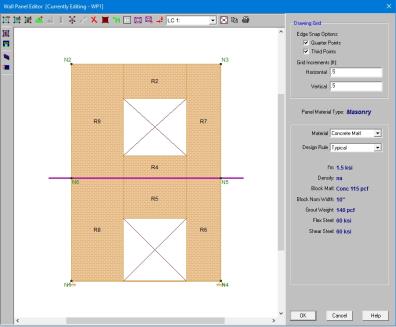
The Wall Panel Editor gives some specific information and options for modeling/analysis of masonry walls.
Masonry Wall Panels will have the following view controls:
 Toggle Region Display allows you to turn the display of regions on or off.
 Toggle Lintel Display allows you to turn the display of lintels on or off.
 Toggle In Plane Reinforcement allows you to turn the display of in plane reinforcement on or off after you have solved your model.
Within the Wall Panel Editor, you have the option of adding rectangular openings to masonry wall panels. To draw an opening, select the Openings button and then select two nodes or grid intersections which make up the two diagonal corners of your opening. When an opening is drawn a lintel is automatically created above the opening. To view or edit the properties of a masonry lintel, double-click inside the boundary of the drawn opening. This will bring up the Editing Properties window for that particular lintel.
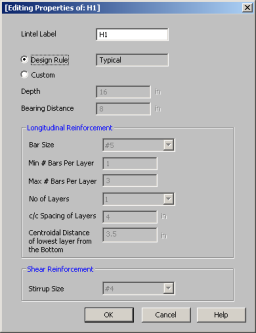
This window will show the design options set in the Wall Design Rules - Lintel spreadsheet to design/analyze your lintel. If you have multiple lintels in a wall and want a specific design that differs from the other lintels, then you can
Here we will walk through the different input options available for designing/analyzing lintels:
Depth - This is the depth of your lintel.
Bearing Distance - This is the bearing length at either end of the lintel. This is used to calculate the effective length of the lintel.
Bar Size - This is the reinforcement size you wish to use for your main reinforcing in the lintel.
Bars Per Layer - This is the number of bars you wish to have in a given layer of reinforcement. There is also an option to have the this value optimized based on geometry of the section and also the number of layers that you have defined.
Number of Rebar Layers - This is an option if you need multiple layers of reinforcement in the lintel.
c/c Spacing of Layers - This is the distance between layers (if there is more than one).
Centroidal Distance of lowest layer from the Bottom - This value is used to calculate the "d" value for the lintel.
Stirrup Size - This is the size of stirrup that will be added to the lintel if required.
Note:
Within the Wall Panel Editor, you have the option of creating rectangular regions within the masonry wall panel. Regions are used to define reinforcement in different parts of the wall. Each region will be assigned a uniform reinforcement, which may be different than the reinforcement in other parts of the same wall.
If no regions have been drawn on a wall then they will be automatically generated when a solution is performed. To automatically generate regions prior to running a solution, click the Generate Wall Regions Automatically button 
To manually draw regions, select the Create New Regions  button and use your cursor to select two nodes or grid intersections which make up the diagonal corners of the region. To exit this tool right-click your mouse.
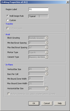
To view or edit the properties of a masonry region, double-click inside the boundary of the drawn region. This will bring up the
The information is populated from the Wall Design Rules spreadsheet for masonry. For more information see the Masonry Wall - Design Rules spreadsheet on setting this up.
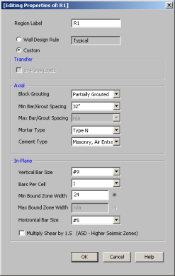
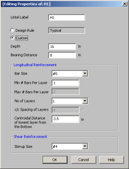
In most cases this Region Editor would only be used as a viewer. If, however, you want to change the reinforcement for a region within the wall to make it different than the Wall Design Rules, you can use the Custom option. When using the custom option the program will now use all of the information set in the Region Editor and will disregard any information given by the design rule.
Note:
Within this dialog you can specify the properties which will be used for the design of the region. The program can optimize the bar spacing and the boundary zone width based on code checks. The block size, reinforcing strength and the method of self-weight calculation are defined in the Design Rules under the Masonry Wall tab.
Here we will walk through the different input options available for designing/analyzing regions:
Transfer - This is an option as to whether or not you want this region to transfer In Plane Loads. If you check these transfer options, the program will dump those loads above and below an opening into the adjacent regions for design.
Note:
- These transfer options are only available when you have defined a region above or below an opening.
- If you do not choose to check these transfer options you will see design results for regions above and below openings.
Axial - Allows you to define properties of a region based on axial forces.
In-Plane - Allows you to define properties of a region based on in-plane forces.
When an opening is drawn in a masonry wall panel, you will notice that a lintel beam region is automatically created above the opening. If you have multiple openings, you may want to merge the individual lintels into one. To do this, select the Merge Lintels  button. If you have two lintels you want to merge, then click within each of the openings to merge them into one. If you have multiple lintels that you want to merge, click inside of the two openings that define the ends of the merged lintel that you want. You will see that this merges your multiple openings into one. To exit out of this tool right-click your mouse.
When merging lintels, the top edges of the lintels have to be identical. If, once you have merged lintels, you delete one of the openings the entire lintel will be deleted. At that point, you have to delete any openings left in the wall that don't have a lintel over them.
The program will optimize masonry walls and lintels based on the required demand forces. The program can optimize:
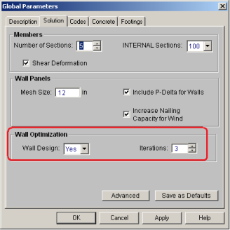
To update the stiffness portion of the wall, the program must re-solve your model with these updated stiffnesses as this will change the distribution of forces through the model. By
By
After the solution is run (with or without optimization) the design results are based on the stiffness used in the last iteration (
The program will always present results in the output that coincide with the stiffness used in the final solution.
Note:
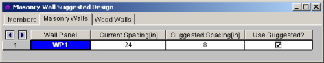
In the Suggested Design spreadsheet you will get a list of wall panels in your model that are not yet fully optimized, showing the vertical bar and/or grout spacing of the last iteration (Current Spacing) and the program optimized spacing (Suggested Spacing). From here you have the ability to Use Suggested? which means that you want to re-run the solution with the Suggested Spacing. You can choose this for each wall panel individually. Once you have these checkboxes checked appropriately, press the  button. After this, the stiffness matrix is re-formulated and may cause some redistribution of loads through the model. Because of this, the Suggested Spacing may also update and you may need to Use Suggested? multiple times to converge on a solution.
Note:
For masonry lintels you must input the dimensions, bar size and number of layers of bars for the lintel, but are given the option of optimizing how many bars are in a given layer. If you provide a max/min number of bars in the Wall Design Rules - Masonry Lintel tab then the program will optimize the number of bars in a layer.
The program will do a check to see that the reinforcement in the lintel will fit properly. The available width for reinforcing in the lintel is based on the width of block, thickness of grout between the block and the reinforcement, and it assumes there will be a double-leg stirrup.

where
Note that we use a minimum bar spacing equal to the minimum of either db or 1".
For masonry regions, there for optimizing.